
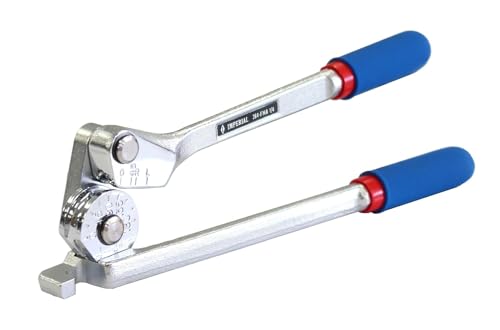
Imperial 364FHA06
$89.97 at Amazon
Check it on AmazonPrice as of Oct 24, 2026, 5:30 AM EDT
Read the sizes and limits
Match the operation, tube size and flare angle.
As an Amazon Associate I earn from qualifying purchases.
A bender changes the tube’s route; a flaring tool forms its end. Pick Imperial 364FHA06 for 3/8-inch OD soft copper bends. For flaring, match the required angle first: the linked RIDGID 377 makes 37° flares, not 45°.
The three Imperial tools each bend one actual outside diameter. The RIDGID bundle pairs a 37° flaring tool with a separate 3/16-inch OD bender. The separate 458R forms 45° SAE flares within its listed material and wall limits.


Product prices and availability are accurate as of the date/time indicated and are subject to change. Any price and availability information displayed on Amazon.com at the time of purchase will apply to the purchase of this product.
| Tool | Key specs | Pick it if | Skip it if |
|---|---|---|---|
| Imperial 364FHA06 | 3/8 in. actual OD, 15/16 in. radius, Up to 180° bends | Your tube is 3/8-inch actual OD and its material and route fit the maker’s bending instructions. | The tube is nominal 3/8-inch water tube, or your job needs a flared connection rather than a change in direction. |
| Imperial 364FHA04 | 1/4 in. actual OD, 9/16 in. radius, Up to 180° bends | You have identified 1/4-inch actual OD tube and need a dedicated lever bender for that diameter. | Your label says nominal 1/4-inch K/L water tube, or you expect one bender to handle several diameters. |
| Imperial 364FHB05 | 5/16 in. actual OD, 11/16 in. radius, Swivel handle, Up to 180° bends | Your tube is 5/16-inch actual OD and the swivel handle suits the planned bend and work area. | You need a 3/8-inch or 1/2-inch opening, or the tool cannot rotate and release in the available space. |
| RIDGID 377 + 403 bundle | 377: 37° flare, 377 hard materials: wall ≤0.035 in., 403: 3/16 in. OD, 403: wall ≤0.06 in., 403: 5/8 in. bend radius | Your system requires a 37° flare on 377-compatible material. For hard copper, steel, stainless steel or brass, the 377 limit is 0.035-inch wall. The 403 separately bends 3/16-inch OD annealed copper, steel or stainless steel with wall thickness at most 0.06 inch. | The equipment requires 45° flares, or you need a bender for the larger sizes shown on the flare bar. |
| RIDGID 458R | Catalog 83037 / model 458R, 45° SAE flare, 1/8–3/4 in. OD: eight listed sizes, Wall ≤0.035 in. (0.9 mm) | Your joint requires a 45° SAE flare on steel, stainless steel, hard copper or brass within the 0.035-inch wall limit and one of the eight listed OD sizes. Confirm the equipment’s finished-flare requirements. | The fitting requires 37°, your tube exceeds the wall limit, or the equipment requires a forming method this model does not establish. |
My call: the Imperial 364FHA06 is the starting pick for repeated bends in 3/8-inch OD soft copper. The model is tied to one opening, so there is no range to interpret. Check the tube marking before choosing it. A nominal 3/8-inch water tube has a different outside diameter and will not fit this selection.
Imperial’s catalog gives the 364-FHA-06 a 15/16-inch radius to the center of the tube. That figure is useful when planning a turn around framing or an adjacent pipe. It describes the bend’s geometry, rather than the room needed to swing the handles or lift the tool away afterward.
The maker describes an open-side lever design that can be placed over the tube at a chosen point. Its angle markings help identify the intended bend, with bends up to 180° listed for the series. Do not read that maximum as a promise that a full return bend will fit inside your cabinet.
For a replacement water line, write down both its nominal size and measured OD. A nominal 1/4-inch K or L water tube has the 3/8-inch OD relevant here. ACR tube uses actual OD in its designation. Read the tube label and check the outside diameter before choosing the matching opening.
This bender changes direction only. It does not cut the tube square, remove a burr or form a connection end. If the line terminates at a flare fitting, the flare angle and finished dimensions remain separate checks. A successful bend does not establish that the end will seal against the fitting.
Before committing a finished length, plan the bend plane and the straight sections needed at each end. Keep the forming area clear of obstructions. If the copper flattens, develops a crease or cracks, stop and replace the affected section. Extra force cannot make a damaged bend acceptable for service.
My call: choose the Imperial 364FHA04 when the copper itself measures 1/4 inch across its outside. That is the job this opening addresses. It is a different tool from the 3/8-inch 364FHA06, even though both belong to the same lever-bender family and have similar photographs.
Imperial’s model table lists a 9/16-inch radius to the center of the tube for the 364-FHA-04. Treat that as a routing dimension. A smaller centerline radius than the 3/8-inch model does not make it a substitute for that model. The tube must fit its own correctly sized groove.
The series uses an open side and a hook to locate the tube. Imperial lists bends through 180° and calibrated angle markings. Those features suit planning a shaped length of tube before final connection. They do not establish a minimum straight length beside an existing flare nut or a particular wall clearance.
A common selection mistake starts with nominal 1/4-inch water tube. CDA’s size convention makes that tube 3/8 inch at the outside, so it belongs with the larger opening. By contrast, tube designated 1/4-inch OD calls for this opening. Keep the two labels separate on your shopping note.
The selected Amazon title says 364FHA04, while the maker’s catalog prints 364-FHA-04 with separators. That identifies the same model row, with one 1/4-inch opening. Confirm the full model on the package. Do not infer a second opening, an adapter or a kit from a different product photograph.
For a tube ending in a flare, leave the end preparation and nut sequence on the work plan. Sliding a nut onto an already bent route may be awkward if clearance is tight. Establish the connection geometry before forming the final piece, and use the equipment’s actual assembly instructions for that joint.
My call: the Imperial 364FHB05 is the size-specific choice for 5/16-inch OD soft copper when the swivel handle is useful. The FHB designation matters. This is not the fixed-handle FHA model, and the 05 suffix does not describe a set of five interchangeable heads.
Imperial’s current FHB table identifies 364-FHB-05 as 5/16-inch OD with an 11/16-inch radius to the tube center. The family page covers several imperial and metric models, but each individual tool bends one size. A heading that says 1/4 to 1/2 inch does not give this particular tool that range.
The handle can be repositioned partway through a bend when the two handles begin to meet. Imperial describes that feature as a way to make bends through 180° without crossing the handles in the usual lever arrangement. It changes handle clearance; it does not change the tube groove or the bend radius.
That distinction matters near a wall. A swivel can help with handle positioning, but the head, hook and tube still need clearance. Plan both the forming movement and the path used to remove the tool. A bend that looks possible in a flat sketch may trap the tool against a fitting.
The 5/16-inch OD opening is not an approximate match for 8 mm tube. Imperial lists metric FHBM models separately, so choose by the actual marked specification rather than a rounded conversion. A close number on a ruler is not maker approval for a different diameter.
Do not choose the swivel version to compensate for an unidentified tube temper. CDA distinguishes soft annealed copper from hard drawn copper, and appropriate bending equipment depends on that distinction. If the tube or service cannot be identified, have a plumber or HVAC professional establish the material and method before work begins.
My call: consider the RIDGID 377 and 403 bundle only after confirming a 37° connection requirement. RIDGID identifies catalog 41162 as model 377, a non-ratcheting 37° SAE flaring tool. Its angle is the deciding limit. It is the wrong cone for a joint that calls for 45°.
The 377 bar lists seven openings: 3/16, 1/4, 5/16, 3/8, 1/2, 5/8 and 3/4 inch. Those are flaring openings. They do not describe the other tool in this package. The included catalog 36117 model 403 bender accepts only 3/16-inch actual OD tube.
RIDGID lists the 403 with a 5/8-inch bend radius and bends up to 180°. Its materials are annealed copper, steel and stainless steel with wall thickness no greater than 0.06 inch. Hard copper is outside that bending recommendation, even when a piece fits the 3/16-inch opening.
The 377 uses an eccentric cone and a clutch that releases during flare formation. Follow its own tube-height and finishing instructions. A clutch is a forming aid, not a check that the angle, outside flare diameter or sealing face meets the connected equipment’s requirements.
RIDGID recommends the 377 for aluminum and soft copper. It also lists hard copper, steel, stainless steel and brass through 0.035-inch wall thickness. Check material and wall thickness alongside the 37° angle before purchase. The 403’s separate 0.06-inch wall limit does not extend the 377’s hard-material limit.
The Amazon title identifies both RIDGID catalog numbers in one bundle, while the maker documents describe the tools separately. Check that the current page still offers both exact models before purchase. The package does not establish approval for refrigerant circuit work, gas service or an automotive brake connection. Keep both model numbers beside the required joint specification.
The RIDGID 458R is the 45° SAE flaring choice here when the tube and joint match its specifications. Catalog number 83037 identifies this ratcheting model. Unlike the linked 377, it forms a 45° flare. It does not supply the separate bender needed to change the tube’s route.
RIDGID’s Precision Ratcheting Flare Tools page lists steel, stainless steel, hard copper and brass through 0.035-inch wall thickness, or 0.9 mm. Check that wall limit before choosing the tool, even when the outside diameter fits. The 403 bender’s larger wall allowance does not apply to the 458R.
The 458R model row lists eight tube sizes: 1/8, 3/16, 1/4, 5/16, 3/8, 1/2, 5/8 and 3/4 inch. These are individual OD openings, rather than an adjustable range accepting any intermediate diameter. Match the marked tube size to a listed opening; do not round a metric measurement to an imperial fraction.
The reversible ratchet lets the feed handle work back and forth. RIDGID describes an eccentric cone and a clutch for forming and smoothing the flare. Those features help operate the tool; they do not verify the fitting angle or approve a finished connection. Inspect the flare against the applicable equipment requirements.
RIDGID’s Precision Flare Tools Instructions, p. 1, starts with a square, reamed tube end and places it even with the bar top. The sheet explains that changing tube height changes flare diameter. Follow that procedure together with the connected equipment’s finished dimensions, rather than copying another maker’s protrusion setting.
Choose the 458R for its documented 45° SAE geometry, not merely because a job involves copper. RIDGID lists its 456R separately for 45° R410A flares. The 458R label alone therefore does not settle a mini-split specification. Have a qualified HVAC professional confirm the equipment’s forming method before refrigerant circuit work.
| Tool | Operation and use | Tube OD | Bend radius or flare angle | Limit | Amazon |
|---|---|---|---|---|---|
| Imperial 364FHA06 | 3/8-inch OD bends | 3/8 in. | 15/16 in. centerline radius | One size; no flare | Check it on Amazon |
| Imperial 364FHA04 | 1/4-inch OD bends | 1/4 in. | 9/16 in. centerline radius | Not nominal 1/4-in. water tube | Check it on Amazon |
| Imperial 364FHB05 | 5/16-inch OD bends | 5/16 in. | 11/16 in. centerline radius | Not an interchangeable-head kit | Check it on Amazon |
| RIDGID 377 + 403 bundle | 37° flare plus separate 3/16-inch bend | 377: 3/16, 1/4, 5/16, 3/8, 1/2, 5/8, 3/4 in. | 377: 37°; 403: 5/8 in. radius | 377: aluminum/soft copper; hard copper, steel, stainless, brass wall ≤0.035 in. 403: annealed copper, steel, stainless wall ≤0.06 in.; no 45° flare | Check it on Amazon |
| RIDGID 458R | 45° SAE flaring only | 1/8, 3/16, 1/4, 5/16, 3/8, 1/2, 5/8, 3/4 in. | 45° SAE | Steel, stainless steel, hard copper, brass; wall ≤0.035 in. (0.9 mm); no bending or 37° flare | Check it on Amazon |
Sort the bender-opening column to compare actual OD. The 377’s seven flare openings are listed separately because they perform a different operation.
Start with the marking on the tube, then confirm the actual outside diameter. A nominal water-tube label and an ACR tube label follow different conventions.
| Tube label or measurement | Actual OD | Selected bender route | Separate end-forming check |
|---|---|---|---|
| 3/16 in. OD | 3/16 in. | 403 in the RIDGID bundle | 377 only if the joint requires 37° |
| 1/4 in. OD ACR | 1/4 in. | Imperial 364FHA04 | Read the equipment’s required flare angle |
| 5/16 in. OD | 5/16 in. | Imperial 364FHB05 | Match the fitting and finished flare |
| Nominal 1/4 in. K/L water tube | 3/8 in. | Imperial 364FHA06, subject to temper | Do not infer connection approval from OD |
| Nominal 3/8 in. K/L water tube | 1/2 in. | None of the selected benders | Identify the connection independently |
| Nominal 1/2 in. K/L water tube | 5/8 in. | None of the selected benders | A 377 opening does not establish the right angle |
| Nominal 3/4 in. K/L water tube | 7/8 in. | None of the selected benders | Outside the selected 377 bar sizes |
CDA describes K, L and M water tube by nominal size, with actual OD 1/8 inch larger. ACR tube is designated by actual OD. The same fraction on two labels can therefore point to different tools. The bender’s opening follows the outside of the tube, not the water-tube trade size.
The matrix shows OD coverage only. A matching opening does not establish the correct temper, wall thickness, bend radius or service. For example, nominal 1/4-inch water tube reaches the 3/8-inch row, but you still need to establish whether its temper is suitable for the selected bender.
A tube marked in millimeters needs the same care. Do not round a measurement to the nearest imperial opening. Imperial publishes separate metric models. Read the exact model’s capacity and check the tube marking before force is applied; a visible mismatch is a reason to stop, not tighten the hook harder.
| What you know | What it establishes | What remains to check |
|---|---|---|
| Annealed / soft | CDA temper designation | Exact tool, tube OD and material limits |
| Drawn / hard | Different temper from soft coil | Equipment expressly suitable for this tube |
| K, L or M | Water-tube category | Does not by itself identify temper or tool approval |
| ACR | Actual-OD designation | Does not approve any particular flare connection |
Soft and hard describe temper, not simply the tube’s diameter. CDA identifies annealed tube as soft and drawn tube as hard. The handbook permits bending both with appropriate equipment. That does not authorize pushing hard tube into a tool intended for soft copper.
For these Imperial picks, the recommendation is limited to correctly identified soft copper within the exact opening. Do not extend that advice to every material named on a broad family page. A hard straight length found behind a fixture needs a separate tool-and-material check before anyone attempts a bend.
Heating hard copper is not a substitute selection method offered here. Torch work changes the safety questions around the line, nearby surfaces and the service. If the only way to make the intended route seems to involve heating installed tubing, have a licensed professional plan the repair and required shutdown.
| Bender | Centerline radius | Twice radius, calculated | What that calculation leaves out |
|---|---|---|---|
| 364FHA04 | 9/16 in. | 1-1/8 in. | Tube outside diameter and tool envelope |
| 364FHB05 | 11/16 in. | 1-3/8 in. | Handle swing and release path |
| 364FHA06 | 15/16 in. | 1-7/8 in. | Fittings and required straight sections |
| RIDGID 403 | 5/8 in. | 1-1/4 in. | Space for tool placement and removal |
Twice the centerline radius describes the center-to-center width of a semicircular bend. The calculated column is geometry, not a measured clearance recommendation. A 364FHA06 return bend can span 1-7/8 inches between centerlines while still needing more room around the outside of the tube and the tool.
For an installed route, check the head position at the start, the handle path during forming and the removal path afterward. The FHB05 swivel changes one part of that movement. It cannot move a wall, reduce the listed 11/16-inch centerline radius or create extra straight tube beside a fitting.
Springback is another reason to avoid guessing a final shape from the scale alone. RIDGID’s 600-series instructions discuss material-dependent overbend, but that setting is not an Imperial setup instruction. Follow the actual bender’s alignment and correction method. Do not use handle extensions to gain leverage; RIDGID’s 600-series instructions prohibit them.
| Check | Why it matters | Selection rule |
|---|---|---|
| Cone angle | 37° and 45° define different mating geometry | Match the equipment or fitting specification |
| Finished flare diameter | The sealing face must meet the required dimensions | Inspect against the actual equipment manual |
| Tube protrusion | Changes how much material the cone forms | Use the exact flaring tool’s setup |
| Nut and seat | They belong to the specified joint | Check together before forming the end |
The cone angle must match the fitting’s seat. A bar opening determines which tube diameter can be clamped; it does not change the cone geometry. Tightening harder cannot correct a mismatched sealing face.
A 45° label alone is also incomplete. The equipment may specify a finished outside diameter, a particular nut and a tightening method. Daikin’s FBA installer guide is one example: it separates tool types in its protrusion table and provides tube-specific finished dimensions. Use the manual for your own equipment rather than borrowing its numbers.
Single flare, double flare and bubble flare are not interchangeable labels for the same formed end. An automotive kit must explicitly make the joint required by the equipment before it enters the choice. A photograph of a flaring bar, or a general copper-compatible claim, cannot settle that question.
| Documented example | Maker setup | Boundary |
|---|---|---|
| RIDGID Precision Flare Tools, model 377 | Tube initially even with bar top; height adjusts flare diameter | Follow 377 instructions and the applicable joint standard |
| Superior Tool 17515 instructions | 1/8 in. above bar | Applies to that specific tool; not a 377 setup |
| Yellow Jacket 60278 | Automatic tube-height gauge | Do not replace its gauge with another tool’s number |
| Equipment manual | May distinguish clutch and wing-nut tools | Finished geometry remains equipment-specific |
RIDGID’s Precision Flare Tools instruction sheet begins with the tube end even with the top of the bar. Its diagram shows that raising or lowering the end changes the finished flare diameter. That is a tool-specific setup and adjustment relationship, not permission to guess the finished joint dimensions.
The 1/8-inch protrusion in the Superior Tool 17515 instructions belongs to that tool. Copying it onto the 377 would ignore a different cone and bar arrangement. Likewise, a tool with an automatic height gauge should be set using its own instructions, rather than a number remembered from a wing-nut tool.
If the tool instructions and the equipment instructions appear to conflict, stop before assembling the joint. Confirm the exact tool type, equipment model and finished-flare requirement with the makers or a qualified installer. Do not resolve a dimensional conflict by applying more torque.
Identify the actual OD first. The selected Imperial openings are 1/4, 5/16 and 3/8 inch. Choose the one that matches the tube and planned radius.
The 377 accepts aluminum and soft copper; its hard copper, steel, stainless steel and brass limit is 0.035-inch wall. The 403 bends 3/16-inch OD annealed copper, steel or stainless steel with wall at most 0.06 inch.
A 45° joint needs a 45° forming tool and the finished dimensions specified by the equipment manual.
Do not cut or form the line until a professional identifies the service and completes the maker’s isolation and depressurizing steps.
A useful tool note has more than a fraction on it. For example, write “soft copper, 3/8-inch actual OD, route change, 15/16-inch tool radius” when that is the verified job. If the same piece ends at a flare seat, add the required angle and the equipment’s joint specification separately.
For several tube sizes, count distinct openings rather than counting tools in a photograph. Buying the 364FHA04 and 364FHA06 covers their two listed diameters only. The FHB05 adds a third. None of those purchases supplies a 1/2-inch or 5/8-inch bender opening.
If all you need is an expanded tube end for a different joining method, first confirm whether the operation is swaging. A swage and a flare produce different ends. Avoid buying a flare tool because a search result groups bending, flaring and swaging under one general tube-working heading.
For loose tube, wear eye protection and clear the work area. For installed water lines, follow the fixture/equipment maker’s shutoff, cooling and pressure-release instructions first. Leave gas, refrigerant and electrical isolation to the appropriate professional.
CDA and RIDGID require a square tube end. Keep the cutter aligned with the tube. A slanted cut leaves a different amount of material around the circumference before the cone starts forming it.
Ream the cut end as directed without damaging the sealing area. Keep debris out of the tube, especially when the equipment requires a clean refrigeration circuit. A visible burr is unfinished preparation.
CDA specifies fitting the flare nut before forming the end. Check its direction and the equipment’s nut requirement. The completed flare prevents sliding a forgotten nut over that end.
A bender and a flaring bar do not correct poor cutting. If the end is visibly slanted, cracked or damaged, resolve that condition before choosing tube protrusion. The same preparation sequence applies whether the later forming operation uses a clutch tool or a different maker-approved mechanism.
For cutter selection, see our pipe cutter guide. Our copper deburring guide explains the separate burr-removal step. Those operations prepare the tube; they do not approve the final flare angle or joint dimensions.
This sequence concerns the linked 37° model 377 on correctly selected, loose tube. It is not a procedure for opening a charged circuit or substituting a 37° tool on 45° equipment.
RIDGID requires checking for binding, wear, missing parts and damage. Stop if a defect is present. Keep its assembled flaring bar together; the maker says not to interchange bars. Follow the equipment safety instructions and use eye protection.
Loosen the screws and move the yoke to the hinged end. Open the bar and use the correct opening. RIDGID’s starting position has the tube even with the bar top; confirm the required finished flare under the applicable joint specification.
Move the yoke over the tube. Align its arrow with the appropriate bar line, then securely tighten the clamp screw in the side dimple as the instructions show. Do not compensate for the wrong opening by extra clamp force.
Turn the feed handle to form the flare. RIDGID directs at least two more full handle rotations after clutch release to smooth it. Retract the cone, loosen the clamp and open the bar. Inspect the flare to the applicable standard before assembly.
| After forming | Accept only after checking | Stop condition |
|---|---|---|
| Angle and size | Required joint geometry and finished dimensions | 37° tool used for a 45° seat |
| Surface | Clean, smooth sealing face | Crack, deep score or debris |
| Shape | Uniform flare around the tube | Lopsided or visibly damaged lip |
| Assembly readiness | Correct nut and undamaged mating seat | Missing nut or unidentified fitting |
A clutch release reports an event in the tool. It does not inspect the fitting or identify which angle your equipment needs. Keep the finished flare visible for inspection before connecting it. If the formed end is cracked, cut back to sound tube and remake it only if the remaining length permits the specified joint.
Tube slippage is a reason to stop and inspect the setup. Check the selected opening, tube diameter, bar condition and clamp placement against the tool instructions. Repeated slipping or excessive force calls for maker support or a qualified professional, rather than improvising a shim inside the bar.
| Location | What governs it | Mistake to avoid |
|---|---|---|
| Tool screws and hinge | RIDGID maintenance instructions | Treating tool lubrication as joint sealant |
| Forming cone | Exact tool instructions and fluid compatibility | Using any oil because another tool mentions oil |
| Flare mating surfaces | CDA and the equipment manual | Applying pipe-joint compound as a generic fix |
| Nut tightening | Equipment’s required method and torque | Copying a torque from a different tube size or system |
RIDGID’s 377 instruction sheet specifies light general-purpose oil on the screws and bar hinge, with excess wiped away. That maintenance instruction is not a direction to coat a flare seat. CDA says not to apply pipe-joint compound to flare mating surfaces.
A tool maker’s cone-lubrication instruction is another separate question. Yellow Jacket’s 60278 procedure discusses cone oil and refrigerant compatibility. Apply the instructions for the actual tool and equipment together. Never choose a lubricant by smell or substitute a solvent around a line without checking its safety directions.
The connected equipment decides the final nut, tightening method and test procedure. Daikin’s example uses a spanner with a torque wrench and model-specific values. No single torque is offered here for all copper flares. Gas and refrigeration testing belongs with a qualified professional and the applicable equipment instructions.
Do not cut a charged line or connect gauges as a practice flaring step. EPA identifies connecting or disconnecting precharged lines and refrigerant hoses among certification-triggering activities. Use an appropriately licensed HVAC professional with the required Section 608 certification.
Have a licensed plumber or gas fitter identify permitted tube, joints and required testing. The gas appliance’s shutoff and ventilation instructions govern isolation. Do not loosen a fitting, vent gas or use a flame to diagnose a connection.
Before work, follow the fixture or equipment maker’s shutoff, cooling and pressure-release steps. A closed valve alone does not prove the tube is depressurized. If isolation cannot be confirmed, stop and call a licensed plumber.
Equipment wiring and circuit changes belong with a licensed electrician and the maker’s power-isolation instructions. A hand-operated tube tool does not make nearby energized equipment safe.
Stop when a bend kinks, a flare cracks or the tube marking cannot be identified. Confirm the material and method before remaking the piece. Do not return a damaged section to service because the nut can still be tightened.
Only if your job requires both operations. The bender changes the tube route; the flaring tool forms an end for its specified seat. A 364FHA06 can bend 3/8-inch OD tube, but it cannot form a flare. A 377 forms 37° flares, but it does not bend the route.
Nominal 1/2-inch K/L water tube has 5/8-inch actual OD under CDA’s sizing convention. None of the selected benders has that opening. Do not choose a 1/2-inch OD tool just because the water-tube label says 1/2 inch. Temper and bending method remain separate checks.
Do not assume so. CDA permits hard copper bending with appropriate equipment, while drawn and annealed tube have different tempers. Our Imperial recommendations here concern soft copper at the exact listed OD. Have a qualified professional establish a suitable method for hard installed tube.
Check the actual OD, groove fit, tube temper and tool instructions before trying again. A wrong opening or unsuitable forming method can leave the tube unsupported or damaged. A creased or collapsed section is a stop condition. Do not hide it behind a fitting or straighten it for reuse.
Check the tool’s required straight section, head clearance and removal path. No universal minimum distance is established for these picks. The FHB05 swivel can change handle position, but it does not shrink its 11/16-inch centerline radius or guarantee access beside a nut.
Flaring creates a shaped lip that meets a matching seat and is held by the specified nut. Swaging expands the tube end for a different connection arrangement. A 377 flare bar and cone do not become a swaging tool because their tube sizes overlap.
The bundle’s 377 makes 37° flares. Do not select it for equipment requiring 45°. Match the exact equipment manual’s angle, finished dimensions and nut requirements first. Refrigerant circuit work also requires the appropriate professional qualifications; the presence of a hand tool does not remove those requirements.
Use the exact tool instructions. RIDGID’s Precision Flare Tools sheet starts the 377 tube even with the bar top, with height changes affecting flare diameter. Superior Tool’s 17515 specifies 1/8-inch protrusion for its own tool. Neither number is a universal setting for every bar and cone.
Stop and inspect the diameter, correct opening, clamp position, bar condition and prepared end against the tool instructions. RIDGID requires correcting tool defects before use. A split flare must be remade from sound tube; additional tightening does not remove the crack or establish an acceptable sealing surface.
Do not use tape or compound to correct a wrong-angle or damaged flare. CDA says not to apply pipe-joint compound to the mating surfaces. Follow the actual equipment’s joint instructions, including any specified lubricant. Tool-screw or cone lubrication is separate from what belongs on the assembled joint.
No. The 377 flare bar lists seven openings from 3/16 through 3/4 inch, with discrete sizes between them. The separate 403 bender accepts 3/16-inch OD tube only. Read those two capacities as separate specifications even though Amazon offers the tools together.
Do not substitute based on a rounded conversion. Imperial lists imperial FHB and metric FHBM tools separately. The selected FHB05 is marked 5/16 inch. Use a tool expressly identified for the tube in your hand, and check the maker’s dual-size approval if one is claimed.
Isaac Daniels, a licensed journeyman plumber in Georgia, owns PlumbingPicks and is responsible for this page. The recommendations connect maker-identified tube sizes and forming geometry to a specific job. They do not imply that a familiar brand makes every cone angle or bender opening interchangeable.
We read the Imperial and RIDGID model information and RIDGID’s forming instructions. We used CDA’s tube-size conventions and equipment-specific flare guidance. On Oct 22, 2026, 1:26 PM EDT, Amazon’s Creators API showed all five new and in stock; photos come from the same API.
Tube OD and flare angle decide the tool, so the tools are listed by job rather than scored. The use labels follow operation, actual OD and flare angle. A tube-size chart cannot replace the equipment manual or a professional’s decision about an installed system.
| Selection check | Rule applied |
|---|---|
| Operation | Bend the route, form a flare or expand an end: establish which first |
| Size | Match actual OD to the exact model opening |
| Geometry | Read centerline radius separately from tool clearance and flare dimensions |
| Safety | No procedure for opening gas or refrigerant circuits; follow maker isolation and PPE steps |
| Offer and photo | Exact branded model; new and in stock at the Oct 22, 2026, 1:26 PM EDT read; API product photo |
| Evidence boundary | Maker documents establish specifications; reader questions shape coverage, not performance claims |